3 day emergency delivery
How Do Absolute Encoders Work?
Absolute Encoders: Single and Multi-Turn
Absolute Encoders:
Single and Multi-Turn
The measuring system consists of a light source, a code disc pivoting in a precision ball bearing and an opto-electronic scanning device.
A LED is used as a light source which shines through the code disc and onto the screen behind.
The tracks on the code disk are evaluated by an opto-array behind the reticle. With every position another combination of slashes in the reticle is covered by the dark spots on the code disk and the light beam on the photo transistor is interrupted. That way, the code on the disc is transformed into electronic signals.
Fluctuations in the intensity of the light source are measured by an additional photo transistor, and another electronic circuit compensates for these. After the electronic signals are amplified and converted they are then available for evaluation.

Single-Turn
Single turn encoder are encoders that specify the absolute position for one turn of the shaft i.e. for 360°. After one turn the measuring range is completed and starts again from the beginning.
Multi-Turn
Linear systems normally need more than one turn of a shaft.
A single turn encoder is unsuitable for this type of application because of the additional requirement of the number of turns.
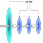
The principle is relatively simple: several single turn encoders are connected using a reduction gear (see image on left side).
The first stage supplies the resolution per turn, the stages behind supply the number of turns.
A single turn encoder is unsuitable for this type of application because of the additional requirement of the number of turns.
The principle is relatively simple: several single turn encoders are connected using a reduction gear (see image on left side).
The first stage supplies the resolution per turn, the stages behind supply the number of turns.
The total number of steps in this example is
16 x 16 x 16 x 8192 steps = 33.554.432 steps Binary 111,1111,1111,1111111111111